Download #
Overview #
Power coming into the property is monitored by a Current Transformer (CT) that clamps around the property’s incoming power cable and is then connected to the charge point.
- The CT has a cable allowing it to be connected to the charge point.
- Additional cable may be added to the CT cable but to maintain a good signal, it is recommended that cables extensions are kept as short as possible.
How to Connect the Wire #
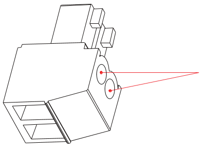
Figure 1
Step 1:
Loosen the two screws with a fat screwdriver (fat head size: 2mm), as shown in the Figure 1.
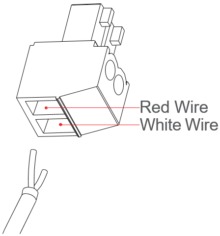
Figure 2
Step 2:
Insert the red wire and white wire into the corresponding holes, as shown on the Figure 2.
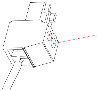
Figure 3
Step 3:
Tighten the two screws with the fat screwdriver (fat head size: 2mm) to crimp the two wires.
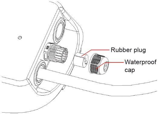
Figure 4
Step 4:
Unscrew the waterproof cap and take out the rubber plug.
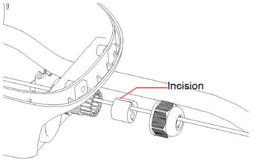
Figure 5
Step 5:
Pass the wire attached to the CT’s jack through the center hole of the waterproof cap, then press it into the rubber plug from the incision, and connect it to the inside of the charger.
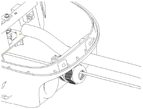
Figure 6
Step 6:
Tighten the waterproof cap.
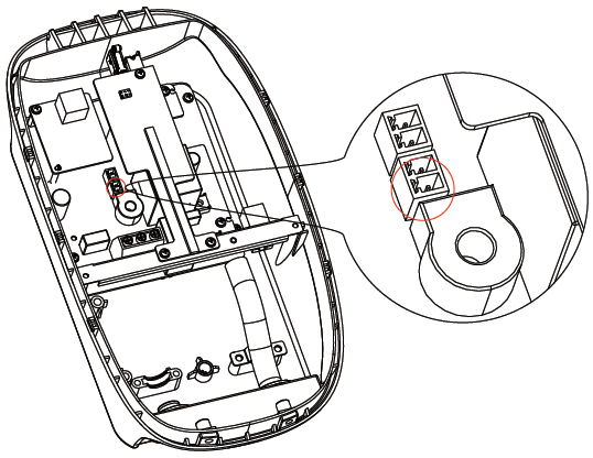
Figure 7
Step 7:
Insert the CT’s jack into the socket as shown on the printed circuit board.
Connect the CT to the Property #
- The CT clamp should be positioned around the phase cable between the Meter and the Consumer Unit.
- The arrow shown on the CT clamp must point in the direction of electrical flow TOWARD the consumer unit.
• Alternatively, if required, the CT clamp may be positioned on the Neutral cable leaving the Consumer Unit. The arrow on the CT clamp must point in the direction of electrical flow AWAY from the consumer unit.
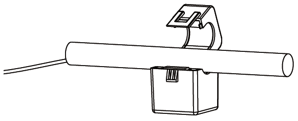
Figure 8
Step 8:
Release the clip on the CT clamp then open the clamp, and place the CT clamp around the power cable.
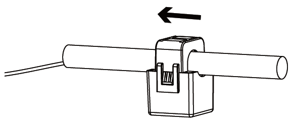
Figure 9
Step 9:
Close the CT clamp and secure it with the clip.

- Make sure the arrow on the clamp points in the correct direction.
- No other cables should pass through the CT clam
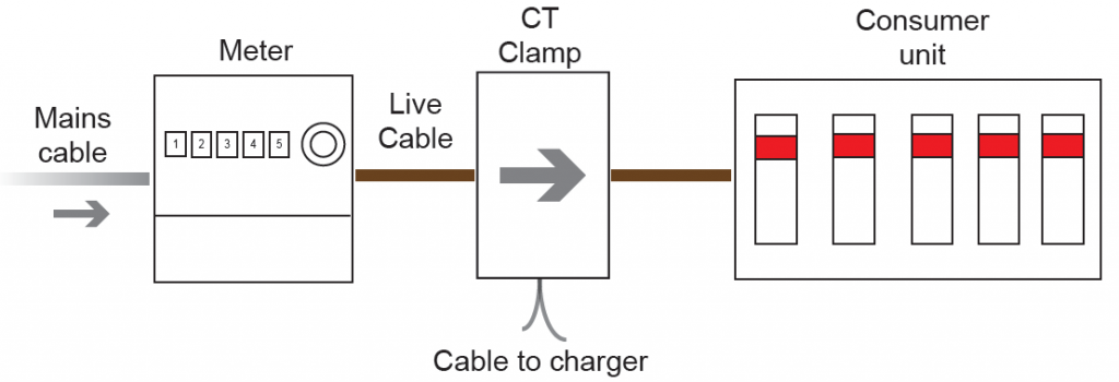
Figure 10 CT Clamp Positioning