Download #
CT Clamp installation #
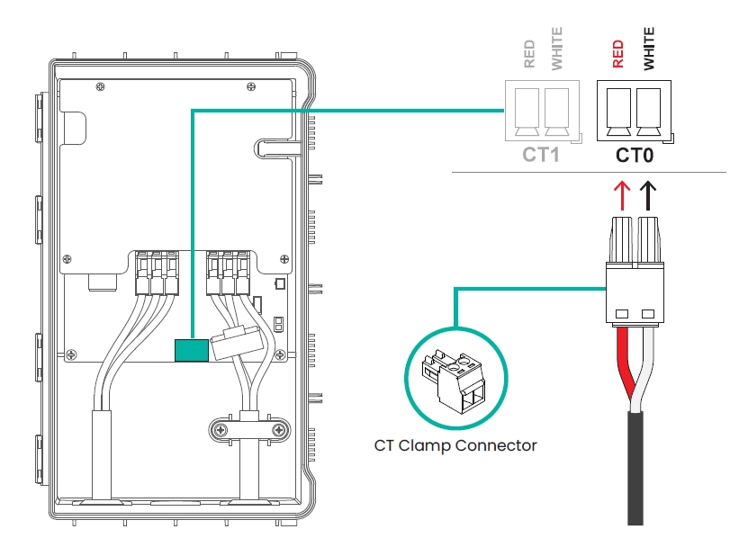
Connect the CT Clamp Cable | Insert the CT clamp cable into the green 2-pin connector. Ensure that the red wire is connected to the left pin and the white wire to the right pin as shown in the illustration image.
Secure the Connector | Firmly press the connector into the CT0 port on the main board. Double-check that the connector is fully seated and matches the pin orientation.
Wiring Note | CT1 port of MX7 is reserved for future use.
* Ensure the power is OFF before connecting the CT clamp. Improper connection may result in incorrect current measurement or device malfunction.
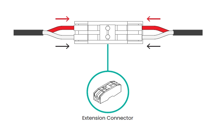
CT Clamp cable extension (optional) #
If additional cable length is needed during CT clamp installation, use the extension connector provided in the accessory box. Connect both ends of the CT cable using the extension connector, as shown in the side view above.
* Ensure that : The connector is securely fastened. The wire polarity (red/white) is correctly maintained.
* Do not modify or splice the CT cable manually. Always use the designated extension connector to ensure measurement accuracy and electrical safety.